Motor Control Board using TinkerCad
1. Introduction
In today’s activity we will use an Arduino and a H-bridge controller to engage a DC motor to move in a postive or negative direction based on a temperature value. This could be useful to move plants, canopy in response to heat from the Sun.
2. RPM, Rad/s, Angular Velocity(Deg/s)
This section provides a quick recap on Revolution Per Minute, Radians Per Second and Degrees per second. Being able to interchange between these values will help visualise.
RPM:
- the number of complete turns (full revolutions) the engine or wheel makes in a one-minute time period
- remember that this is only per minute, not per second like many other measures of rotation.
Rad/s:
- A radian is a measure of an angle
- defined in terms of π
- 2π radians (rad) in a complete revolution
- You can relate this to degrees by noting that 360 degrees = 2π rad, so 1 radian = 57.3 degrees.
So lets assume that we have a RPM of 1000, and that this needs to be converted to Rad/s. The two main steps in the conversion are converting RPM to revolutions per second (RPS), then converting total revolutions to the angle covered in radians. The first step is simple: Divide the number in RPM by 60 to find the number of revolutions per second as shown in the equation 1:
\[ \begin{aligned} RPS &= \frac{RPM}{60 seconds/minute} \\ \\ \Rightarrow 16.67 RPS &= \frac{1000}{60} \end{aligned}\tag{Eqn:1} \]
Now we need to convert the RPS to Rad/s,you take RPS and convert to radians by multiplying by 2π, as seen in the equation 2:
\[ \begin{aligned} rad/s &= RPS \cdot 2\pi \\ \\ \Rightarrow 104.72 rad/s &= 16.67 \cdot 2\pi \end{aligned}\tag{Eqn:2} \]
Therefore we can combine equations 1 and 2 above into one equation 3 below:
\[ \begin{aligned} rad/s &= RPM \cdot \frac{2\pi}{60} \\ 104.72 rad/s &= 1000 \cdot \frac{2\pi}{60} \end{aligned}\tag{Eqn:3} \]
Now that we rad/s we can calculate the angular velocity (deg/s). There are two ways to achieve this both methods are shown below in equations 4 and 5.
Equation 4 first takes the approach using the knowledge that \(1 rad/s = 57.2958^{\circ}\) and you have precalulated using equation 3.
\[ \begin{aligned} deg/s &= rad/s \cdot 57.2958^{\circ} \\ \Rightarrow 628.32^{\circ}/s &= 104.72 rad/s \cdot 57.2958^{\circ} \end{aligned}\tag{Eqn:4} \]
Equation 5 replaces the \(2\pi\) with 360 in *Equation 3
\[ \begin{aligned} deg/s &= RPM \cdot \frac{360}{60} \\ 628.32^{\circ}/s &= 1000 \cdot \frac{360}{60} \cdot 57.2958^{\circ} \end{aligned}\tag{Eqn:5} \]
3. Setting up the circuit
Once loaded login to TinkerCad and then click on Circuits > Create new Circuit
Change the circuit name, located top-left hand side of the screen to Direction_Control_DC_Motor_TMP36, see below.
Next you need to add an Arduino Uno and a breadboard that need to be connected together from the 5V and GND pins of the Arduino to the power and ground rails of the breadboard.
Next you need to add an Arduino Uno and a breadboard that need to be connected together from the 5V and GND pins of the Arduino to the power and ground rails of the breadboard.
This can be achieved by either selecting the Arduino Uno and the breadboard from\ Components > Basic components or by changing Components > Basic to Components > Starter and choosing Arduino Uno and the Breadboard starter. Please refer the image below.
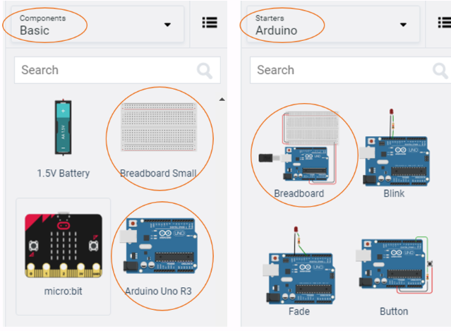
If you have chosen the Arduino and breadboard template from the Components > Starter then these two components are already connected with a corresponding 5V line(red) and GND line.
You now need to add:
- 1 x TMP36 sensor, Components > Basic at the bottom or alternatively use the search box
- 1 x resistor, set at 1k\(\Omega\) or 1000\(\Omega\), Components > Basic first component in the list
- 1 x L293D, H-bridge Motor Driver, Components > All in the last item in Power control section of the list or alternatively use the search box
- 1 x DC Motor, Components > Basic, 14th item in the list, or alternatively use the search box
- 1 x 9V D-Cell Battery, Components > Basic, 7th item in the list, or alternatively use the search box.
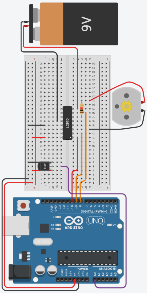
Placing components (refer to the image below):
-
Place the TMP36 so that the Power and GND is in row 4 and 6 column h respectively. Take a wire from the Vout to on row 5 column g to pin A0 of the Arduino Uno.
-
Place the L293D chip so that the white dot (enable 1 & 2 pin) is in row 12 and column e, therefore the pin labeled Power 2 should be in row 19 column e. You should have bridge between both sides of the breadboard.
-
Staying with L293D, create a red wire at row 12 column j into the + line the same row, this connects L293D Power 1 pin to the Arduino 5V line.
-
Next create a black wire at row 15 column j into the - of the same row, so this connects the L293D Ground pin to the Arduino GND line.
-
Create a new red wire just below the Enable 1 & 2 pin of the L293D at row 12 column d, to pin 10 of the Ardunio Uno.
-
Create an orange wire at row 13 column c, below Input 1 pin of the L293D, to pin 9 of the Arduino Uno.
-
Create an orange wire at row 18 column d, below Input 2 pin of the L293D, to pin 8 of the Arduino Uno.
-
Get the 9V Battery and places it in vertical alignment using the rotate button top left of the control panel, so that it is parallel to the breadboard on the opposite side the Arduino Uno.
-
Create a red wire from the Positive terminal of the battery and connect it to row 19 column d, just below the L293D Power 2 pin.
-
Similarly create a black wire from the Negative terminal of the battery and connect it to row 16 column g, just above the other L293D Ground pin.
-
Now place the DC motor underneath the breadboard, between rows 13 and 25
-
Continuing with the DC motor, take a black wire from Terminal 1 of the DC motor and connect it to row 14 column a, inline with L293D Output 1.
-
Similarly take a red wire from Terminal 2 of the DC motor and connect it to row 20 column a
-
Lastly, take the resistor set to \(1k\Omega\), and rotate so that it lies horizontally, and connect Terminal 1 pin to the row 17 column c, inline with L293D Output 2, therefore Terminal 2 of the resistor should be connected to row 21 column c
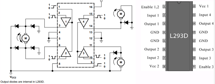
For reference look at the below image for L293D functional block diagram and pin layout.
4. Programming The Circuit
-
Once you have completed the circuit you will need to programme the Arduino Uno. Located above Components click the Code Text.
-
Once sketch has appeared reproduce the following code:
4.1 Globale variables
-
Now you are ready to set up all the Sketch up as follows.
-
Firstly the variables are declared and initialised using the
#definekeyword. -
Lines 1 to 3, define the variables
en 10,in1 9andin2 8will reference the physical connections of the L293D Enable 1 & 2, Input 1 and Input 2 respectively. -
Line 4, define the variable
temp A0will reference the physical connection of the TMP36Voutpin.
-
-
Now declare the following dynamic variables are declared and initialise them using data types
int,floatandbool.... #define temp A0 int pwmOutput = 12; float tempValue; float temperature; float rads = 0.0; float degrees = 0.0; bool movedRight = false; bool movedLeft = false; ... void setup()-
Line 6,
int pwmOutput = 12;, will stores the value that will be used in theanalogWrite()function. -
Lines 7 and 8, variables
float tempValue; float temperature;will store theanalogRead()value and the converted temperature value respectively. -
Lines 9 and 10, variables
float rads =0.0;andfloat degrees = 0.0;will store the calculated values for radians per second and degrees per second respectively. -
Lines 11 and 12, variables
bool movedRight = false;andbool movedLeft = false;are used to stop the motor turning continuously.
-
-
Script should now look like the below:
4.2 void setup
-
The
void setup()will be used to set the pin modes and initialise the serial.void setup() { Serial.begin(9600); pinMode(en, OUTPUT); pinMode(in1, OUTPUT); pinMode(in2, OUTPUT); }-
Line 16's code,
Serial.begin(9600);, sets the Serial speed at 9600 bits per second (bps) -
Line 17's code,
pinMode(en, OUTPUT);, sets pin 10 on the Arduino Uno as an output so that a signal can be sent to the Enable 1 & 2 pin of the L293D chip. -
Line 18's and 19's code,
pinMode(in1, OUTPUT);pinMode(in2, OUTPUT), sets pin 9 and 8 on the Arduino Uno as an output so that a signal can be sent to the Input 1 & 2 pin of the L293D chip respectively.
-
-
Script should now look like the below:
Code
#define en 10 #define in1 9 #define in2 8 #define temp A0 int pwmOutput = 12; float tempValue; float temperature; float rads = 0.0; float degrees = 0.0; bool movedRight = false; bool movedLeft = false; void setup() { Serial.begin(9600); pinMode(en, OUTPUT); pinMode(in1, OUTPUT); pinMode(in2, OUTPUT); } void loop() { }
4.3 void loop
-
Reproduce the following code below:
void loop() { tempValue = analogRead(temp); temperature = ((tempValue*(5.0/1024.0))-0.5)/0.01; if( temperature <= 30.0 && movedRight == false) { motorInstructions(); debugger(); digitalWrite(in1, LOW); digitalWrite(in2, HIGH); delay(1000); digitalWrite(in2, LOW); movedRight = true; movedLeft = false; } else if ( temperature >= 40.0 && movedLeft == false) { motorInstructions(); debugger(); digitalWrite(in1, HIGH); digitalWrite(in2, LOW); delay(1000); digitalWrite(in1, LOW); movedLeft = true; movedRight = false; } }-
Starting with line 24, the code
tempValue = analogRead(temp);will read the TMP36 wired to pin A0 of the Arduino, and convert voltage to the Analogue Digital Converted value. -
Remember the that voltage rang is 0V to 5V and the ADC of the Arduino is 10-bits, so its range is 0 - 1023.
-
Line 25's code,
temperature = ((tempValue*(5.0/1024.0))-0.5)/0.01;}, converts the thetempvalue, (0 - 358) to Celsius with a range of \(-40^{\circ}C\) to \(125^{\circ}C\), see equation 6.
\[ \begin{aligned} temperature = \cfrac{\left(\left(tempValue \cdot \left( \cfrac{5.0V}{1024}\right)\right)-0.5\right)}{0.01}\\ \Rightarrow 26.17^{\circ}C = \cfrac{\left(\left(156 \cdot \left( \cfrac{5.0V}{1024}\right)\right)-0.5\right)}{0.01} \end{aligned}\tag{Eqn:6} \]
-
-
Now that the
temperaturevalue has been calculated, lines 27 and 39 can be explained.-
Line 27's code,
if( temperature <= 30.0 && movedRight == false), checks to see if thetemperatureis less than or equal to,<=, 30.0. If this condition istruethen the second part of the conditional statement can be checked, using&&. the boolean (true or false) variablemovedRight == falseis compared for equality==, remember a single=means assign the right hand side to the left hand side. Now if both conditions are true then the code between lines 29 and 37 will be executed. If either statement is false, then then line 39 is executed. -
Line 39's code is much the same as line 27's, but the
temperaturehas to be greater or equal to,>=, 40.0 andmovedLeftmust be false. If both statements are true then lines 41 to 49 are executed, if not then the programme loops back to the line 24, and the process starts again.
-
-
Now we can look inside lines 29 to 30 & lines 40 to 49, you probably can see that there are only a few differences between the two blocks of code. We will look at lines 29, 30, 41 and 42 later.
-
Lets look at lines 32, 33 and 44 and 45, where the two sets of lines are polar opposites of each other. The
digitalWrite(in1, LOW);digitalWrite(in1, HIGH);&digitalWrite(in2, LOW);digitalWrite(in2, HIGH);changes the direction the motor spins. -
Looking at the block diagram of the L293D, we can see that Input 1, and Input 2, both pin 3 and 7 on the L293D change the direction of the motor.
-
Lines 34 and 46 code,
delay(1000),allowing the motor to turn in that direction for 1 second. -
Lines 36, 37 & 48, 49 both set the
movedLeftandmovedRightvariables true or false.
-
-
Now it is time to return to lines 29 & 41, both sets of lines do the same things so look below at the code for
motorInstructions();, add to end of the script after the closing}of thevoid loop().void motorInstructions() { rads = 53.0 * (2*3.1415926/60.0); degrees = rads * 57.2958; analogWrite(en, pwmOutput); }-
Let's first look at line 55's code,
rads = 53.0 * (2*3.1415926/60.0);, calculates the radians per second using equation 3. Where \(\pi\) is shown to 7 decimal places. The53.0the average speed the DC motor in response to the resistors value of \(1k\Omega\). -
Line 56's code,
degrees = rads * 57.2958;, which is taken from equation 4, to calculate the degrees per second. -
Line 57's code,
analogWrite(en, pwmOutput);, outputs the PWM signal,pwmOutputvalue of 12 to theenpin, to the Enable 1 & 2 pin of the L293D. The value ofen, 12, again is preset because of the resistors value of \(1k\Omega\).
-
-
So lastly, lets look at the function
debugger();called on lines 30 and 42 of thevoid loop()function.void debugger() { Serial.print("Temperature: "); Serial.print(temperature); Serial.print(" | RAD/s: "); Serial.print(rads); Serial.print(" | Degree/s: "); Serial.println(degrees); }
5. Extensions
-
Now you have a better understanding of the circuit and the code ...
-
What happens to the motor when the resistance value is changed? Adjust line 55's rpm value to match the motors rpm value.
-
With the knowledge that each line of code takes some time to execute, specifically mathematical functions. Would pre calculating all of the constants in an equation speed up the programme? Try it.
-
Explore the code, make changes to experiment with different temperature values, timings, conditional statements (if, else if).
-
6 Full code
Code: Full code is seen below
Code: Full code is seen below
#define en 10
#define in1 9
#define in2 8
#define temp A0
int pwmOutput = 12;
float tempValue;
float temperature;
float rads = 0.0;
float degrees = 0.0;
bool movedRight = false;
bool movedLeft = false;
void setup()
{
Serial.begin(9600);
pinMode(en, OUTPUT);
pinMode(in1, OUTPUT);
pinMode(in2, OUTPUT);
}
void loop()
{
tempValue = analogRead(temp);
temperature = ((tempValue*(5.0/1024.0))-0.5)/0.01;

if( temperature <= 30.0 && movedRight == false)
{
   motorInstructions();
   debugger();

   digitalWrite(in1, LOW);
   digitalWrite(in2, HIGH);
   delay(1000);
   digitalWrite(in2, LOW);
   movedRight = true;
   movedLeft = false;
}
else if ( temperature >= 40.0 && movedLeft == false)
{
   motorInstructions();
   debugger();

   digitalWrite(in1, HIGH);
   digitalWrite(in2, LOW);
   delay(1000);
   digitalWrite(in1, LOW);
   movedLeft = true;
   movedRight = false;
}
}
void motorInstructions()
{
rads = 53.0 * (2*3.1415926/60.0);
degrees = rads * 57.2958;
analogWrite(en, pwmOutput);
}
void debugger()
{
Serial.print("Temperature: ");
Serial.print(temperature);
Serial.print("  | RAD/s: ");
Serial.print(rads);
Serial.print("   | Degree/s: ");
Serial.println(degrees);
}
7. Full circuit
-
If you have struggled to get there.... here is full project you can tinker with: