Introduction
In today’s activity we will study how computers “count”, and we will discuss the idea of binary numbers and binary counting.
We will then connect the Arduino board to 4 LEDs, and see how the computer can count.
1. Binary Counting
Computers count in BINARY, i.e. using ones and zeros. For example, the number 5 in binary is 00000101. How does this work? Here is a chart to explain how the computer uses 8-bits to represent the numbers from 0...255.
Below is a table that show the possible combinations of 4-bit binary numbers and their decimal equivalent.
*Bite binary represented here is MSB to LSB |
2. Converting between Decimal <---> Binary
Since binary is a base-2 system, each digit represents an increasing power of 2, with the rightmost digit representing 20 , the next representing 21, then 22, and so on. To determine the decimal representation of a binary number simply take the sum of the products of the binary digits and the powers of 2 which they represent.
Below are some examples as reminders.
The decimal number `10' is converted to binary form like so:
\[ \begin{matrix} 2^3 & 2^2 & 2^1 & 2^0\\ \hline 8 & 4 & 2 & 1 \\ 1 & 0 & 1 & 0 \end{matrix} \]
Alternatively you can achieve the same result this way too:
\[ [(1) \cdot 2^{3}] + [(0) \cdot 2^{2}] + [(1) \cdot 2^{1}] + [(0) \cdot 2^{0}] \ \]
\[ 1 \cdot 8 + 0 \cdot 4 + 1 \cdot 2 + 0 \cdot 1 \]
\[ 1 0 1 0 \]
So therefore decimal `10' is 1010 in binary form.
The binary number 11011011 is converted to decimal form like so:
\[ \begin{matrix} 2^7 & 2^6 & 2^5 & 2^4 & 2^3 & 2^2 & 2^1 & 2^0\\ \hline 128 & 64 & 32 & 16 & 8 & 4 & 2 & 1 \\ 1 & 1 & 0 & 1 & 1 & 0 & 1 & 1 \\ \end{matrix}\\ 219 = 128+64+16+8+2+1 \]
Alternatively you can achieve the same result this way too:
\[ [(1) \cdot 2^{7}] + [(1) \cdot 2^{6}] + [(0) \cdot 2^{5}] + [(1) \cdot 2^{4}] + [(1) \cdot 2^{3}] + [(0) \cdot 2^{2}] + [(1) \cdot 2^{1}] + [(1) \cdot 2^{0}] \]
\[ [1 \cdot 128] +[1 \cdot 64] + [0 \cdot 32] + [1 \cdot 16] + [1 \cdot 8] +[0 \cdot 4] + [1 \cdot 2] + [1 \cdot 1] \]
\[ 219 = 128+64+16+8+2+1\]
3. Settting up the Circuit
Once loaded login to TinkerCad and then click on Circuits > Create new Circuit.
Change the circuit name, located top-left hand side of the screen to 8-bit Binary Counter, see below:
Next you need to add an Arduino Uno and a breadboard that need to be connected together from the 5V and GND pins of the Arduino to the power and ground rails of the breadboard.
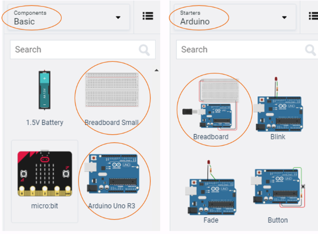
This can be achieved by either selecting the Arduino Uno and the breadboard from Components > Basic components or by changing Components > Basic to Components > Starter and choosing Arduino Uno and the Breadboard starter. Please refer to the image below.
If you have chosen the Arduino and breadboard template from the the Components > Starter then these two components are already connected with a corresponding red 5V line and GND line.
You will need:
- 8 x LED, any colour
- 8 x resistor, set at \(0.22k\Omega\) or \(220\Omega\)
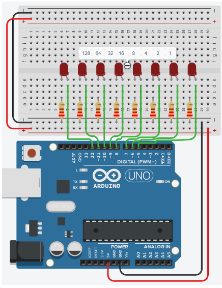
Placing components (refer to image below step by step instructions):
- Place the LEDs so that the cathode and anode is in row 6 and 7 column e respectively. Repeat for the next 7 LEDs with rows 8, 11, 14, 17, 20, 23, 26 as gaps between each LED.
- Place the resistors inline with the Cathode of the LED so that terminal 2 is in column b and terminal 1 in the GND rail.
- connect a wire from inline with each Anode of LED, and connect from left to right of the breadboard, to Pins 12, 11, 10, 9, 8, 7, 6, 5 in the Arduino Uno.
4. Programming the Circuit
-
Once you have completed the circuit you will need to programme the Arduino Uno. Located above the Components click the Code > Text.
-
Once the sketch has appeared reproduce the following code:
-
Now you are ready to set up all the Sketch up as follows.
int ledPin[8]={5,6,7,8,9,10,11,12};
char binary[9] ={0,0,0,0,0,0,0,0,'\0'};

void setup()
{

}

void loop()
{

}
4.1 Void Setup
-
Setting up the
void setup()we will do something a little more efficient to set thepinMode()of theledPinsarray.void setup() { Serial.begin(9600); for(int x=0;x<8;x++) { pinMode(ledPin[x], OUTPUT); Serial.print(ledPin[x]); Serial.print(","); } Serial.println(); }-
Line 10, shows the initialisation of a for loop ,
for(int x=0;x<8;x++), sets a variablexas 0 and whilexless than 8 incrementxby 1, so we can repeat the code between the{}8 times. -
Important note, arrays start from 0 to n. So
ledPins[1] = 6andledPins[7] = 12.*
\[ \begin{matrix} Index[x] & 0 & 1 & 2 & 3 & 4 & 5 & 6 & 7\\ \hline LedPin Value & 5 & 6 & 7 & 8 & 9 & 10 & 11 & 12 \\ \end{matrix} \]
- So you can see that as
xstarts at 0,ledPin[x]will set pin 5 asOUTPUT. So thereforeSerial.print(ledPin[x])outputs the value to the Serial monitor.
-
4.2 void loop
-
The
void loop(), function has little code because of the for loop and a user defined functiondisplayBinary();.void loop() { for (byte counter =0;counter<=255; counter++) { displayBinary(counter); delay(500); } } -
So now lets look at the user defined function
displayBinary();below.... displayBinary(counter); delay(500); } } void displayBinary(byte numToShow) { for (int i =0;i<8;i++) { if (bitRead(numToShow, i)==1) { binary[7-i] = '1'; digitalWrite(ledPin[i], HIGH); } else { binary[7-i] = '0'; digitalWrite(ledPin[i], LOW); } } Serial.print("Number: "); Serial.print(numToShow); Serial.print(" | Binary: "); Serial.println(String(binary)); }-
Remember in earlier weeks of the module you looked at the number of bits in different data types?
-
Notice that the expected argument in the
displayBinary(byte numToShow);is the data typebyte. -
So line 31,
for(int i=0; i<8; i++)iterates over the number bits in one byte (8 bits to a byte).
-
Line 33,
if (bitRead(numToShow, i)==1)passes thenumToShowvariable to the inbuilt functionbitRead();. Theifstatement checks to see if the bitiis a 1. -
Line 35,
binary[7-i] = '1';sets the value at the index7-i. -
Line 36,
digitalWrite(ledPin[i], HIGH);sets the LED at the correct bit position toHIGH. -
Therefore line 38,
elsecondition is implicitly true when(bitRead(numToShow, i)==0). -
Line 40,
binary[7-i] = '0';sets the value at the index7-i. -
Line 41,
digitalWrite(ledPin[i], LOW), sets the LED at the correct bit position toLOW. -
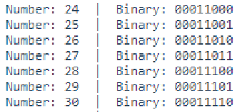
Line 44 to 47, outputs the current number
numToShowand binary equivalent to the Serial monitor. As seen in image below.
- Below shows the output you'd expect to see for the decimal number 171.
\[ \begin{matrix} Arduino pins & 12 & 11 & 10 & 9 & 8 & 7 & 6 & 5\\ LEDs &\circledast & \bigcirc & \circledast & \bigcirc & \circledast & \bigcirc & \circledast & \bigcirc \\ Binary &1 & 0 & 1 & 0 & 1 & 0 & 1 & 0 \\ \end{matrix} \]
-
Look at the following documentation for
bitRead()and summaries in your own words what it does: https://www.arduino.cc/reference/en/language/functions/bits-and-bytes/bitread/ -
Edit line 2 so that it says
char binary[8] ={0,0,0,0,0,0,0,0};and then start the simulation. What difference was there from the original output? Once tested return the code on line 2 tochar binary[9] = {0,0,0,0,0,0,0,0,'\0'};. -
What would the output be on line 47
Serial.println(String(binary)), if lines 35 and 40binary[7-i]is changed tobinary[i]. Test your theory/answer.
- Append the circuit to show 9-bits.
- Adjust the code to match the circuit
- Increase the arrays length by one on lines 1 and 2
- Therefore line 8,
for(int x=0;x<8;x++),x<8needs to be increase by one to match the changes made on lines 1 and 2. - Line 21,
for (byte counter =0;counter<=255; counter++)needs to updated to show a range from 0 to a 9-bit number. Use the formula \((2^9 - 1)\) to find the value you need. - Adjust line 30
for (int i =0;i<8;i++)so that it is the same as line 8. - Finally modify lines 34 and 39
binary[7-i] =,8-i.
-
Does the cicuit and code output a 9-bit number?
-
Reflect on this project, focus on the difficulty of the circuit and code.
4.3 Full Code
Code: Full code
int ledPin[8]={5,6,7,8,9,10,11,12}; char binary[9] ={0,0,0,0,0,0,0,0,'\0'}; void setup() { Serial.begin(9600); for(int x=0;x<8;x++) { pinMode(ledPin[x], OUTPUT); Serial.print(ledPin[x]); Serial.print(","); } Serial.println(); } void loop() { for (byte counter =0;counter<=255; counter++) { displayBinary(counter); delay(500); } } void displayBinary(byte numToShow) { for (int i =0;i<8;i++) { if (bitRead(numToShow, i)==1) { binary[7-i] = '1'; digitalWrite(ledPin[i], HIGH); } else { binary[7-i] = '0'; digitalWrite(ledPin[i], LOW); } } Serial.print("Number: "); Serial.print(numToShow); Serial.print(" | Binary: "); Serial.println(String(binary)); } -
5. Full circuit
-
If you have struggled to get there.... here is full project you can tinker with: