PWM Workbook: Configuring PWM on the ATmega328P
1. Introduction to PWM on ATmega328P
PWM is a technique to control the average power supplied to electronic components by varying the duty cycle of a square wave. The ATmega328P offers several timers that can generate PWM signals. In this workbook, we focus on using Timer0 to generate an 8-bit PWM signal on OC0A (Pin PD6).
2. Timer0 Registers for PWM
TCCR stands for Timer/Counter Control Register. On the ATmega328P and similar microcontrollers, these registers control the behavior of each timer/counter module.
Each timer has one or more TCCR registers that configure aspects such as:
- PWM mode (e.g., Fast PWM, Phase Correct PWM)
- Compare Output Mode (inverting or non-inverting PWM signal)
- Clock source and prescaler (e.g., no prescaler, prescaler of 8, 64, etc.)
2.1 Types of TCCR Registers on ATmega328P
The ATmega328P has three timers, each with associated TCCR registers:
-
Timer0(8-bit):TCCR0AandTCCR0B: These control the settings forTimer0, including PWM configuration, clock selection, and output modes.
-
Timer1(16-bit):TCCR1AandTCCR1B: These controlTimer1, which supports 16-bit resolutions. This is useful for applications needing finer control, such as precise PWM or high-resolution counters.
-
Timer2(8-bit):TCCR2AandTCCR2B: These controlTimer2, similar toTimer0but with different prescaler and clock source options.
2.2 TCCR0A - Timer/Counter Control Register A
| Bit | 7 | 6 | 5 | 4 | 3 | 2 | 1 | 0 |
|---|---|---|---|---|---|---|---|---|
| Name | COM0A1 | COM0A0 | COM0B1 | COM0B0 | - | - | WGM01 | WGM00 |
-
COM0A1: Compare Output Mode forOC0A.-
Setting
COM0A1to 1 enables non-inverting PWM output onOC0A(PinPD6).
-
-
WGM01andWGM00: Waveform Generation Mode.- Setting both
WGM01andWGM00to 1 putsTimer0in Fast PWM mode.
- Setting both
2.3TCCR0B - Timer/Counter Control Register B
| Bit | 7 | 6 | 5 | 4 | 3 | 2 | 1 | 0 |
|---|---|---|---|---|---|---|---|---|
| Name | FOC0A | FOC0B | - | - | WGM02 | CS02 | CS01 | CS00 |
CS02:CS00: Clock Select bits.- Sets the prescaler to control the PWM frequency.
- Example: Setting
CS01andCS00to 1 (CS01 | CS00) applies a prescaler of 64 to the timer.
3. Prescalers
The prescaler in the ATmega328P (and similar microcontrollers) is a divider that reduces the main system clock frequency to a lower frequency for the timer. The prescaler allows you to control the frequency of the timer, which directly affects the speed of operations like PWM or delays that the timer generates.
3.1 Purpose of the Prescaler
The microcontroller’s main clock frequency is often quite high (e.g., 16 MHz on the ATmega328P). Running the timer directly at this speed would result in very high-frequency signals, making it challenging to create longer delays or lower-frequency PWM signals. The prescaler helps by slowing down the timer, making it easier to generate slower or more manageable signals.
3.2 How the Prescaler Works
The prescaler takes the main clock frequency and divides it by a specified factor, which is then used as the input clock for the timer. For example, if the system clock is 16 MHz and the prescaler is set to 64, then the timer operates at:
\[250,000\ Hz\ =\ \frac{16,000,000\ Hz}{64}\]
This effectively slows down the timer and allows more extended timing intervals or lower-frequency PWM output.
3.4 Prescaler Options on ATmega328P
Each timer on the ATmega328P has several prescaler options, typically selectable by configuring specific bits in the TCCR (Timer/Counter Control Register).
| Prescaler | Timer |
|---|---|
| No Prescaling | 1 |
| No Prescaling(direct clock input) | 0, 2 |
| 8 | 0, 1, 2 |
| 64 | 0, 1, 2 |
| 256 | 0, 1, 2 |
| 1024 | 0, 1, 2 |
3.5 Example Calculation of PWM Frequency with a Prescaler
When using Fast PWM mode on an 8-bit timer, the PWM frequency can be calculated as:
\[PWM\ Frequency\ =\ \frac{CPU\ Clock\ Frequency}{Prescaler\ \cdot 256}\]
For example, with a 16 MHz CPU clock and a prescaler of 64:
\[976\ Hz \approx\ \frac{16,000,000\ Hz}{64\cdot 256}\]
This frequency can then be adjusted by changing the OCR(OCR0A) (Output Compare Register) values to control the duty cycle, with the prescaler setting determining the overall timing speed of the signal.
To set the prescaler for Timer0 on the ATmega328P, you configure the CS00, CS01, and CS02 bits in the TCCR0B register. Each combination of these bits determines a different prescaler value. Here’s how you can configure Timer0 for prescalers of 8, 64, 256, and 1024.
3.6 Setting the Prescaler for Timer0
| CS02 | CS01 | CS00 | Prescaler |
|---|---|---|---|
| 0 | 0 | 1 | No prescaler (direct clock) |
| 0 | 1 | 0 | 8 |
| 0 | 1 | 1 | 64 |
| 1 | 0 | 0 | 256 |
| 1 | 0 | 1 | 1024 |
The following code snippets show how to set each prescaler in TCCR0B:
TCCR0B = (1 << CS01); // Prescaler = 8

TCCR0B = (1 << CS01) | (1 << CS00); // Prescaler = 64

TCCR0B = (1 << CS02); // Prescaler = 256

TCCR0B = (1 << CS02) | (1 << CS00); // Prescaler = 1024
4. Building the pwm.c source code
- Remember to include in your
PATHavr-gcc,avrdudeandmake - Open
~/.bashrcand add the following lines, then save and run the commandsource ~/.bashrcto update the current session with the newPATH- Uni machines
# ~/.bashrc export PATH=$PATH:"/c/ProgramData/arduino-ide-v2/Local/Arduino15/packages/arduino/tools/avr-gcc/7.3.0-atmel3.6.1-arduino7/bin" export PATH=$PATH:"/c/ProgramData/arduino-ide-v2/Local/Arduino15/packages/arduino/tools/avr-dude/6.3.0-arduino17/bin" export PATH=$PATH:"/c/Program Files/GCC-Windows-MingW-2.0.0/w64devkit/bin" - Your personal windows machine
# ~/.bashrc export PATH=$PATH:"/c/Users/YOURUSERNAME/AppData/Local/Arduino15/packages/arduino/tools/avr-gcc/7.3.0-atmel3.6.1-arduino7/bin" export PATH=$PATH:"/c/Users/YOURUSERNAME/AppDataLocal/Arduino15/packages/arduino/tools/avr-dude/6.3.0-arduino17/bin" export PATH=$PATH:"/c/Program Files/w64devkit/bin" - You can install w64devkit from here:
- Uni machines
4.1 Basic pwm.ino
Now we have an understanding of the what is going on under the hood we can convert this pwm.ino into and embedded version.
int pwmPin = 6;      // LED connected to digital pin 9

void setup() {
    pinMode(pwmPin, OUTPUT);  // sets the pin as output
    analogWrite(ledPin, 127); // analogRead values go from 0 to 1023, analogWrite values from 0 to 255
}

void loop(){}
Let’s have a breakdown of what this is doing incomparison to the embedded version:
-
PWM Configuration:
-
Using
analogWrite(pwmPin, 127);automatically configures PWM on pin 6 with a duty cycle of 50% (127 out of 255). -
analogWrite()abstracts away the details of configuring the timer registers (likeTCCR0AandTCCR0B) and prescalers, making it simpler but less flexible.
-
-
PWM Frequency and Prescaler:
-
With
analogWrite(), you don’t have control over the prescaler or the PWM frequency. Arduino’s default frequency forTimer0(used for pins 5 and 6) is typically around 976 Hz on an ATmega328P running at 16 MHz. -
In the examples below, we can manually set
TCCR0B, we will choose between different prescalers to adjust the PWM frequency. This will allow for finer control over the PWM signal characteristics.
-
4.2 Create pwm.c
-
Create a new directory inside
embeddedCcalledpwm -
Create a new file inside the the
pwmdirectory calledpwm.c -
Now it’s time start wrighting out the program:
#include <avr/io.h> #include <util/delay.h> void PWM_Init() { // Set PD6 (OC0A) as output DDRD |= (1 << PD6); // PWM pin 6 // Set Timer0 to Fast PWM mode with non-inverting output on OC0A TCCR0A = (1 << COM0A1) | (1 << WGM01) | (1 << WGM00); // Set the prescaler to 64 for Timer0 TCCR0B = (1 << CS01) | (1 << CS00); // Initialize with 0% duty cycle OCR0A = 0; } int main() { PWM_Init(); // Initialize PWM on PD6 while (1) { // Adjust OCR0A as needed for duty cycle from 0 to 255 OCR0A = 127; // Example: 50% duty cycle } }- Setting PD6 as Output:
- line 7
DDRD |= (1 << PD6);configures PD6 as an output pin to output the PWM signal.
- line 7
- Configuring Timer0 for Fast PWM Mode:
- line 10 TCCR0A:
(1 << COM0A1): Sets non-inverting mode for PWM on OC0A.(1 << WGM01) | (1 << WGM00): Sets Fast PWM mode.
- line 13 TCCR0B:
(1 << CS01) | (1 << CS00): Sets a prescaler of 64, controlling the PWM frequency. . Setting the Duty Cycle:
- line 16 OCR0A: Controls the duty cycle. A value of 127 provides approximately a 50% duty cycle.
- Range:
OCR0Acan range from 0 to 255, where:- 0: 0% duty cycle (always low)
- 127: 50% duty cycle
- 255: 100% duty cycle (always high)
- line 10 TCCR0A:
- Setting PD6 as Output:
-
We are now going to copy the
Makefilefrom theblink/created last time, and replace all instances ofblinkwithpwmusing the regex feature: -
Inside vim type the following an press enter to find all instances of
blinkwithpwm -
Remember like with blink we need to compile and upload the code to the board, ensure it is plugged in, to find the com port on windows:
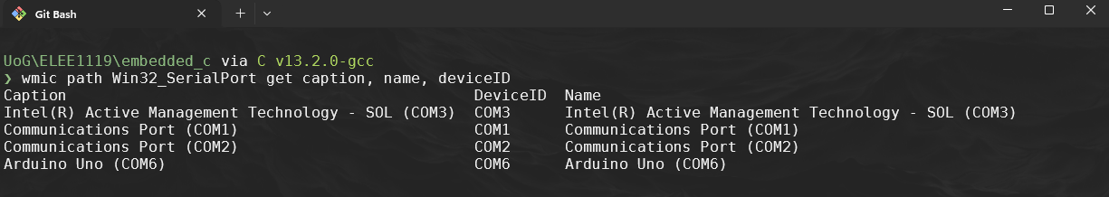
-
If the COM port has changed remember to change it in the
Makefile -
Use
make:make cleanmakemake upload
-
Ensure you have wired up an led circuit in to pin 6 with a 220\(\Omega\) resistor
5. Exercises
5.1 Exercise 1: Changing the Duty Cycle
Modify the OCR0A register in the main loop to create different duty cycles. For example, try setting it to 64, 127, and 192. Observe how the brightness of an LED connected to PD6 changes.
Task:
- Set
OCR0A = 64;// ~25% duty cycle - Set
OCR0A = 192;// ~75% duty cycle - Record the observed LED brightness.
5.2 Exercise 2: Creating a Smooth Fade Effect
Modify the code to gradually increase the duty cycle from 0 to 255 and then decrease it back to 0 to create a smooth “breathing” LED effect.
Hint:
-
Use a
forloop to incrementOCR0Afrom 0 to 255, adding a delay between each increment. -
Then, use another
forloop to decrement it from 255 back to 0.Suppress code here… [32 lines]
#include <avr/io.h>
#include <util/delay.h>

void PWM_Init()
{
    // Set PD6 (OC0A) as output
    DDRD |= (1 << PD6); // PWM pin 6

    // Set Timer0 to Fast PWM mode with non-inverting output on OC0A
    TCCR0A = (1 << COM0A1) | (1 << WGM01) | (1 << WGM00);

    // Set the prescaler to 64 for Timer0
    TCCR0B = (1 << CS01) | (1 << CS00);

    // Initialize with 0% duty cycle
    OCR0A = 0;
}

int main()
{
    PWM_Init(); // Initialize PWM on PD6

    while (1) {
        for (uint8_t i = 0; i <= 255; i++) {
            OCR0A = i;
            _delay_ms(10); // Adjust delay as needed
        }
        for (uint8_t i = 255; i > 0; i--) {
            OCR0A = i;
            _delay_ms(10); // Adjust delay as needed
        }
    }
}
5.3 Exercise 3: Changing the PWM Frequency
Experiment with different prescaler values to change the PWM frequency. Change the CS02:CS00 bits in TCCR0B to see the effects.
Task:
- Try prescalers of 8, 64, and 256, and observe how the frequency and brightness change.