ADC
In this chapter, you will learn how to build a script for reading analog values from the ATmega328P using its ADC (Analog-to-Digital Converter) and output these values to the command line using the USART. This guide will explain the necessary registers and ports related to the ADC.
-
Make sure you have completed the UART Chapter as you will need to print out the data for retrieved from the ADC.
-
All the information below is synthesised and expanded upon from the Data sheet page 202 onwards.
1. Understanding ADC Registers and Ports
The ATmega328P has a built-in Analog-to-Digital Converter (ADC) that can convert analog signals to digital values. The ADC uses several registers to configure its operation:
1.2 ADMUX Register Overview
The ADMUX register is used to configure the ADC (Analog-to-Digital Converter) on the ATmega328P. It allows you to select:
- The reference voltage for the ADC.
- The input channel from which the ADC reads the analog value.
1.3 Bit Structure of ADMUX
The ADMUX register is an 8-bit register, where each bit has a specific purpose:
| Bit 7 | Bit 6 | Bit 5 | Bit 4 | Bit 3 | Bit 2 | Bit 1 | Bit 0 |
|---|---|---|---|---|---|---|---|
| REFS1 | REFS0 | ADLAR | MUX3 | MUX2 | MUX1 | MUX0 |
- REFS1, REFS0: These bits select the reference voltage.
- MUX3, MUX2, MUX1, MUX0: These bits select the ADC input channel
1.4 ADMUX (ADC Multiplexer Selection Register):
-
REFS1:REFS0: Selects the reference voltage for the ADC. We use AVcc (5V) as the reference in our script.
-
MUX3:MUX0: Selects the ADC channel to read from. ADC0 is selected when all MUX bits are 0.
The MUX3:MUX0 bits in the ADMUX register select the ADC input channel:
MUX3 MUX2 MUX1 MUX0 Selected ADC Channel 0 0 0 0 ADC0 (PC0) 0 0 0 1 ADC1 (PC1) 0 0 1 0 ADC2 (PC2) 0 0 1 1 ADC3 (PC3) 0 1 0 0 ADC4 (PC4) 0 1 0 1 ADC5 (PC5) 0 1 1 0 ADC6 (PC6) 0 1 1 1 ADC7 (PC7) 1 0 0 0 Temperature sensor 1 1 0 0 1.1V internal reference 1 1 0 1 GND -
Use these settings to select the appropriate input channel for your ADC conversions.
-
We also look at the internal temperature sensor too!
-
1.5 Example 1: Setting the Reference Voltage to AVcc
-
(1 << REFS0)shifts1to the position of the REFS0 bit (bit 6). -
This sets REFS0 to
1and all other bits to0. -
Bitwise Result:
ADMUX = 0b01000000REFS0 = 1(Reference voltage = AVcc)MUX3:MUX0 = 0000(ADC0 channel selected by default)
1.6 Example 2: Setting the Reference Voltage to AVcc and Selecting ADC3
(1 << REFS0): Sets the REFS0 bit (bit 6) to1(Reference voltage = AVcc).(1 << MUX1): Sets the MUX1 bit (bit 1) to1.(1 << MUX0): Sets the MUX0 bit (bit 0) to1.- The
|operator combines these settings, setting bitsREFS0,MUX1, andMUX0to1, while keeping other bits at0. - Bitwise Result:
ADMUX = 0b01000011REFS0 = 1(Reference voltage = AVcc)MUX3:MUX0 = 0011(ADC3 channel selected)
1.7 Reminder of Bitwise operations
-
(1 << REFS0)- Operation:
1is shifted left by 6 positions (since REFS0 is bit 6). - Result:
0b01000000
- Operation:
-
(1 << MUX1)- Operation:
1is shifted left by 1 position (since MUX1 is bit 1). - Result:
0b00000010
- Operation:
-
(1 << MUX0)- Operation:
1is shifted left by 0 positions (since MUX0 is bit 0). - Result:
0b00000001
- Operation:
-
Combining with the
|(or) Operator(1 << REFS0) | (1 << MUX1) | (1 << MUX0):0b01000000 | 0b00000010 | 0b00000001 = 0b01000011
1.6 ADCSRA (ADC Control and Status Register A):
-
ADEN: ADC Enable. Set this bit to enable the ADC.
-
ADSC: ADC Start Conversion. Set this bit to start an ADC conversion.
-
ADPS2:ADPS0: ADC Prescaler Select Bits. These bits determine the division factor between the system clock and the ADC clock. We use a prescaler of 128 for accurate readings.
-
ADC: This register holds the result of the ADC conversion. It is a 10-bit register divided into two 8-bit registers, ADCL (low byte) and ADCH (high byte).
Prescaler: is a factor by which the system clock is divided to obtain the ADC clock. The ADC clock frequency can be calculated using the formula: \[ADC_{Clock}\ =\ \frac{Sytem\ Clock}{Prescaler}\] So \(\therefore \) \[125kHz\ =\ \frac{16000000}{128}\]
- 125 kHz is within the recommended range of 50 kHz to 200 kHz.
- A prescaler of 128 ensures that the ADC operates at an optimal frequency for accurate 10-bit conversions.
- Larger the prescaler the longer for conversions, lower frequencies are faster but are less accurate due to errors
2. Building a program to grab the internal temperature of the chipset
Temperature Sensor and ADC Setup:
- The internal temperature sensor is connected to a single-ended ADC input.
- The MUX[4..0] bits in the ADMUX register should be configured to select the temperature sensor.
- The internal 1.1V voltage reference must be used as the ADC reference.
The voltage sensitivity is approximately 1LSB/°C and the accuracy of the temperature measurement is ±10°C using
manufacturing calibration values (TS_GAIN, TS_OFFSET)
Typical values for temperautre at set temperatures:
| Temp | Hex | Dec |
|---|---|---|
| –40°C | 0x010D | \(269_{10}\) |
| +25°C | 0x0160 | \(352_{10}\) |
| +125°C | 0x01E0 | \(480_{10}\) |
We can create a linear relationship between the ADC value and the temperature based on the given typical values. Assuming a linear relationship, we can use the following formula:
\[Temperature(^\circ C)\ =\ (ADC_{value}-Offset) \cdot Scale\ Factor\]
-
Create a new directory called
internalADCTempand navigate to it and then create a file calledinternalADCTemp.c: -
Modify the
internalADCTemp.cfile with the following code:Reproduce the code below… […65 lines]
#include <avr/io.h> #include <util/delay.h> #include <stdlib.h> // For itoa() #define USART_BAUDRATE 9600 #define BAUD_PRESCALER (((16000000UL / (USART_BAUDRATE * 16UL))) - 1) // Constants based on typical values #define ADC_AT_25C 352 // ADC value at +25°C (0x0160) #define TEMPERATURE_SENSITIVITY 1 // 1 LSB/°C void USART_Init() { UBRR0H = (BAUD_PRESCALER >> 8); UBRR0L = BAUD_PRESCALER; UCSR0C = (1 << UCSZ01) | (1 << UCSZ00); // 8 data bits, 1 stop bit, no parity UCSR0B = (1 << RXEN0) | (1 << TXEN0); // Enable RX and TX } void USART_Transmit(uint8_t data) { while (!(UCSR0A & (1 << UDRE0))); // Wait until the data register is empty UDR0 = data; } void USART_SendString(char* str) { while (*str) { USART_Transmit(*str++); } } void ADC_Init() { // Set the reference voltage to internal 1.1V and select the temperature sensor ADMUX = (1 << REFS1) | (1 << REFS0) | (1 << MUX3); // Enable the ADC and set the prescaler to 128 ADCSRA = (1 << ADEN) | (1 << ADPS2) | (1 << ADPS1) | (1 << ADPS0); } uint16_t ADC_Read() { ADCSRA |= (1 << ADSC); // Start conversion while (ADCSRA & (1 << ADSC)); // Wait for conversion to complete return ADC; // Return the ADC value } int main() { char buffer[10]; // Buffer to store temperature as a string USART_Init(); // Initialize USART ADC_Init(); // Initialize ADC while (1) { // Read the ADC value from the temperature sensor uint16_t adcValue = ADC_Read(); // Calculate the temperature based on typical values // Using a simple linear conversion with 1 LSB/°C sensitivity int16_t temperature = adcValue - ADC_AT_25C; // Offset from 25°C temperature += 25; // Adjust to get the temperature in °C // Convert temperature to string and send it via USART itoa(temperature, buffer, 10); // Convert temperature to string (base 10) USART_SendString("Temperature: "); USART_SendString(buffer); USART_SendString(" C\n"); _delay_ms(1000); // Delay for demonstration } } -
Once you have saved the script, you can now make the
MakefileReproduce the code below… […27 lines]
MCU = atmega328p F_CPU = 16000000UL CC = avr-gcc CFLAGS = -Os -mmcu=$(MCU) -DF_CPU=$(F_CPU) OBJCOPY = avr-objcopy AVRDUDE = avrdude AVRDUDECONFIG="C:\ProgramData\arduino-ide-v2\Local\Arduino15\packages\arduino\tools\avrdude\6.3.0-arduino17\etc\avrdude.conf" PORT = COM6 BAUD = 115200 PROGRAMMER = -c arduino -p $(MCU) -P $(PORT) -b $(BAUD) all: internalADCTemp.hex internalADCTemp.hex: internalADCTemp.elf $(OBJCOPY) -O ihex -R .eeprom $< $@ internalADCTemp.elf: internalADCTemp.o $(CC) $(CFLAGS) -o $@ $< internalADCTemp.o: internalADCTemp.c $(CC) $(CFLAGS) -c -o $@ $< upload: internalADCTemp.hex $(AVRDUDE) -C $(AVRDUDECONFIG) $(PROGRAMMER) -U flash:w:internalADCTemp.hex clean: rm -f internalADCTemp.o internalADCTemp.elf internalADCTemp.hex -
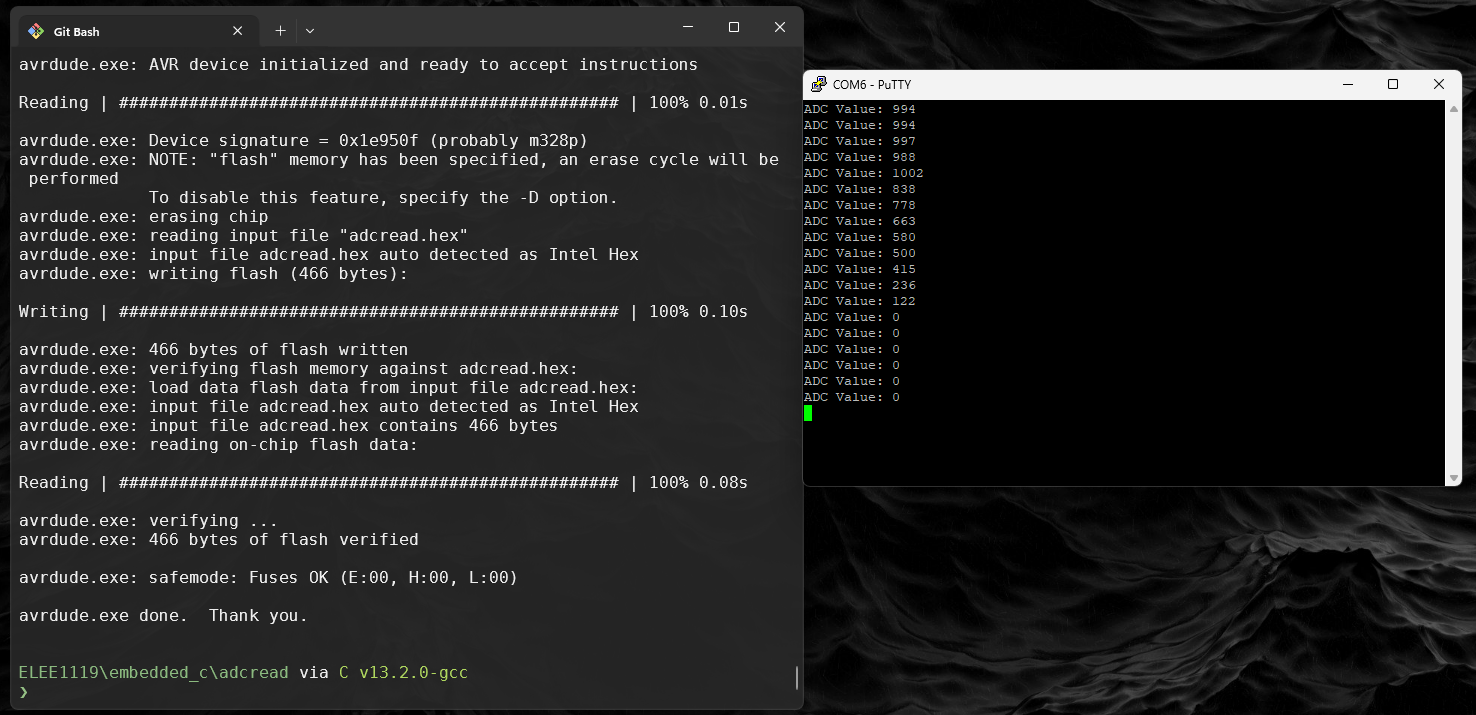
You can now compile and upload and use putty like you did in ADC,
-
make -
make upload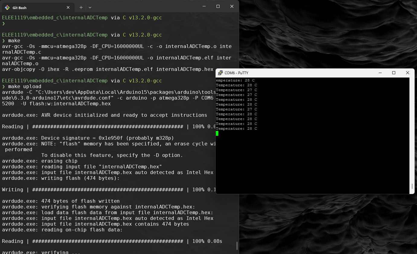
-
3. So how to access the A0-5 pins
Now, let’s write the script step by step:
-
Initialize the ADC:
- Configure the reference voltage and select the ADC channel using the ADMUX register.
- Enable the ADC and set the prescaler using the ADCSRA register.
-
Read from the ADC:
- Start the ADC conversion.
- Wait for the conversion to complete and read the ADC value.
-
Send the ADC Value via USART:
- Convert the ADC value to a string.
- Send the string over serial communication.
-
Create a new directory called
adcreadand navigate to it and then create a file calledadcread.c: -
Modify the
adcread.cfile with the following code:Reproduce the code below… […51 lines]
#include <avr/io.h> #include <util/delay.h> #include <stdlib.h> // For itoa() #define USART_BAUDRATE 9600 #define BAUD_PRESCALER (((16000000UL / (USART_BAUDRATE * 16UL))) - 1) void USART_Init() { UBRR0H = (BAUD_PRESCALER >> 8); UBRR0L = BAUD_PRESCALER; UCSR0C = (1 << UCSZ01) | (1 << UCSZ00); // 8 data bits, 1 stop bit, no parity UCSR0B = (1 << RXEN0) | (1 << TXEN0); // Enable RX and TX } void USART_Transmit(uint8_t data) { while (!(UCSR0A & (1 << UDRE0))); // Wait until the data register is empty UDR0 = data; } void USART_SendString(char* str) { while (*str) { USART_Transmit(*str++); } } void ADC_Init() { ADMUX = (1 << REFS0); // Reference voltage = AVcc, ADC0 channel selected ADCSRA = (1 << ADEN) | (1 << ADPS2) | (1 << ADPS1) | (1 << ADPS0); // Enable ADC, prescaler = 128 } uint16_t ADC_Read() { ADCSRA |= (1 << ADSC); // Start conversion while (ADCSRA & (1 << ADSC)); // Wait for conversion to complete return ADC; } int main() { char buffer[10]; // Buffer to store ADC value as a string USART_Init(); // Initialize USART ADC_Init(); // Initialize ADC while (1) { uint16_t adcValue = ADC_Read(); // Read ADC value itoa(adcValue, buffer, 10); // Convert ADC value to string (base 10) USART_SendString("ADC Value: "); USART_SendString(buffer); USART_SendString("\n"); _delay_ms(1000); // Delay for demonstration } } -
Copy the
Makefilefrom../internalADCTemp/Makefiletoreadadc/and use the regex:%s/\<internalADCTemp\>/adcread/g -
Compile, upload to the board and monitor with putty
makemake upload