ADC2PWM
- Make sure you have completed the following chapters:
Like we did for C_Library/ADCLibrary/PWMLibrary/ADCtoPWM we are going to combine the adc.rs and and pwm.rs capabilities and examples/adc_read.rs and examples/pwm_test.rs.
Mapping adc to pwm
-
To map we need to get the relationship between adc and the period to get the duty cycle, as seen below:
\[ \text{duty_cycle_ns} = \frac{\text{adc_value} \cdot \text{period_ns}}{4095} \]
-
This has been implemented in the
pwm.rsin the last chapter, for reference here is code snippet for the function:
We are going to create a script that utlises what we did for ~/examples/adc.rs and examples/pwm_test.rs.
-
Create a file called
~/bbb-rust/examples/adc2pwm.rsand reproduce the following code:Code: examples/adc2pwm.rs [44 lines]
use std::thread; use std::time::Duration; use bbb_io::adc::{self, AdcPin}; use bbb_io::pwm::{self, Pwm}; fn main() -> bbb_io::BbbResult<()> { let pwm = Pwm::init("P9_14")?; let period_ns = 1_000_000; // 1 ms = 1 kHz pwm.set_period(period_ns)?; pwm.set_duty_cycle(0)?; pwm.enable()?; println!("Phy: {}", pwm.physical_pin); println!("Channel: {}", pwm.channel); println!("Chip: {}", pwm.chip); println!("Period path: {}", pwm.period_path.display()); println!("Duty Cycle path: {}", pwm.duty_cycle_path.display()); println!("Enable path: {}", pwm.enable_path.display()); for _ in 0..30 { let raw = adc::read_raw(AdcPin::A0)?; let mut volts = 0.0; adc::to_voltage(raw, &mut volts)?; let duty_cycle = pwm::map_adc_to_duty_cycle(raw as u16, period_ns)?; println!( "ADC Reading: {raw:4}, Voltage: {volts:.3} V, Duty Cycle: {duty_cycle} ns" ); pwm.set_duty_cycle(duty_cycle)?; thread::sleep(Duration::from_secs(1)); } pwm.disable()?; pwm.cleanup()?; Ok(()) }This example uses the IIO buffer interface rather than repeatedly reading
in_voltage0_raw.The key line is:
let mut adc = BufferedAdc::open(AdcPin::A0, 16)?;This configures the kernel buffer and opens
/dev/iio:device0.The loop then repeatedly reads binary samples:
let raw = adc.read_raw()?;and converts each value to voltage:
adc::to_voltage(raw, &mut voltage)?;The buffer is configured once, then reused:
open buffer once read many samples cleanup automatically -
Build and run the program:
-
Setup the following circuit, which is an amalgamation of ADC and PWM circuits
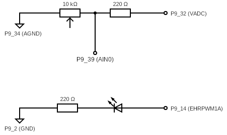
The BeagleBone Black ADC input range is 0 V to 1.8 V.
Do not connect 3.3 V directly to an ADC input pin.
If using a 3.3 V source, use a voltage divider or a safe external 1.8 V reference.
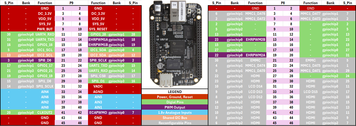
-
When running
./adc2pwmyou may see this terminal output and you have connected up your circuity correctly, the LED should change it’s brightness based on the resistance from the potentiometer:If you see:
echo 0 | sudo tee /sys/bus/iio/devices/iio\:device0/buffer/enableand then re-run the program.
or:
You may need elevated permissions to configure or read from the IIO buffer depending on your system permissions:
sudo ./adc_continuous_readPhy: P9_14 Channel: 0 Chip: 0 Period path: /sys/class/pwm/pwmchip0/pwm0/period Duty Cycle path: /sys/class/pwm/pwmchip0/pwm0/duty_cycle Enable path: /sys/class/pwm/pwmchip0/pwm0/enable ADC Reading: 1536, Voltage: 0.675 V, Duty Cycle: 375091 ns ADC Reading: 1537, Voltage: 0.675 V, Duty Cycle: 375335 ns ADC Reading: 1536, Voltage: 0.675 V, Duty Cycle: 375091 ns ADC Reading: 626, Voltage: 0.275 V, Duty Cycle: 152869 ns ADC Reading: 258, Voltage: 0.113 V, Duty Cycle: 63003 ns ADC Reading: 0, Voltage: 0.000 V, Duty Cycle: 0 ns ADC Reading: 0, Voltage: 0.000 V, Duty Cycle: 0 ns ADC Reading: 308, Voltage: 0.135 V, Duty Cycle: 75213 ns ADC Reading: 635, Voltage: 0.279 V, Duty Cycle: 155067 ns ADC Reading: 1078, Voltage: 0.474 V, Duty Cycle: 263247 ns ADC Reading: 1456, Voltage: 0.640 V, Duty Cycle: 355555 ns ADC Reading: 2093, Voltage: 0.920 V, Duty Cycle: 511111 ns ADC Reading: 2565, Voltage: 1.127 V, Duty Cycle: 626373 ns ADC Reading: 3390, Voltage: 1.490 V, Duty Cycle: 827838 ns ADC Reading: 4023, Voltage: 1.768 V, Duty Cycle: 982417 ns ADC Reading: 4094, Voltage: 1.799 V, Duty Cycle: 999755 ns ADC Reading: 4094, Voltage: 1.799 V, Duty Cycle: 999755 ns ... -
Once you have done that, experiment with the code, can you get a faster response, or a longer run time of the program?