PWM C Library
- You need to have finished:
-
Without the overlay you will not have access to
/sys/class/pwm/pwmchip0
On platforms like the Arduino Uno, the PWM signal typically uses an 8-bit resolution, meaning the duty cycle can range from 0 to 255. This represents the fraction of time the signal is "high" within a given period, where 0 is 0% duty cycle (always off), and 255 is 100% duty cycle (always on).
The BeagleBone Black (BBB), however, is more flexible and powerful regarding PWM control due to its more advanced processor (AM335x). Let's discuss the differences and what this means for using PWM on the BeagleBone Black.
1: PWM on BeagleBone Black
-
PWM Period and Duty Cycle on BeagleBone Black:
-
Period: The total duration of one PWM cycle. It is set in nanoseconds (ns) on the BeagleBone Black.
-
Duty Cycle: The amount of time within the period that the signal is high. This is also set in nanoseconds (ns).
-
-
Setting the PWM Parameters:
-
Unlike the Arduino Uno, where the frequency (period) of the PWM signal is generally fixed by the underlying timer hardware (e.g., ~490 Hz for analogWrite() function), the BeagleBone Black allows for explicit control over both the period and the duty cycle.
-
Default Configuration: You must set it explicitly, as the period defines the frequency of the PWM signal. This is crucial because PWM control on the BeagleBone Black is much more versatile and supports a wider range of frequencies, from a few Hz to MHz.
-
-
Frequency and Duty Cycle Range:
-
Period (Frequency): The BeagleBone Black allows you to set the PWM period to a wide range. The minimum and maximum period (and hence frequency) are determined by the clock settings and the capabilities of the eHRPWM (enhanced High-Resolution PWM) modules. Common period values range from a few nanoseconds to several milliseconds. Larger frequencies are for motors etc, where as lower frequencies for LEDs etc, it is all about the resistive load.
further examples...
-
In motor control applications, a low PWM frequency might cause a whining noise, while a higher frequency (above 20 kHz) would result in quieter operation.
-
In digital audio applications, a higher PWM frequency allows for better reconstruction of an analog waveform from the PWM signal.
-
In a buck converter, a higher PWM frequency can reduce the ripple voltage seen at the output, resulting in a cleaner DC output.
-
In a DC-DC converter, increasing the switching frequency allows for smaller inductors and capacitors, which can reduce the size and cost of the overall design.
-
In high-power applications, engineers balance switching frequency to optimize efficiency, minimize thermal losses, and ensure reliable operation.
-
In sensitive communication systems, switching frequencies are carefully chosen to avoid interfering with data transmission.
-
For an LED dimming application, a frequency of 1 kHz or higher is commonly used to prevent visible flicker
-
In a three-phase motor drive, the PWM signals for each phase must be synchronized at the same frequency to ensure smooth motor operation and prevent electrical noise.
-
-
Duty Cycle Resolution: The duty cycle is not limited to an 8-bit range like the Arduino Uno's 0-255. Instead, it is specified in nanoseconds and can be any value between 0 and the period value. This allows for a much finer resolution of PWM control.
-
-
BeagleBone Black's PWM DAC-like Behavior:
-
The BeagleBone Black does not have a built-in Digital-to-Analog Converter (DAC) like some microcontrollers, but PWM can be used to simulate analog output. By changing the duty cycle of a PWM signal at a high frequency, you can create a voltage level that appears analog when averaged over time.
-
The "DAC" resolution is effectively determined by the timer's clock speed and the period you set for the PWM signal. For example, if you set a period of 1,000,000 ns (1 ms, which corresponds to 1 kHz frequency) and a duty cycle of 500,000 ns (0.5 ms), you get a 50% duty cycle. If you change the period to 2,000,000 ns (2 ms, 500 Hz) while keeping the duty cycle at 1,000,000 ns (1 ms), the perceived output will change.
-
-
Examples
-
Period (period):
- The period of the PWM signal is the total time it takes to complete one cycle (both high and low phases).
- It is specified in nanoseconds (ns) in the sysfs interface.
- For example, a period of 1,000,000 ns corresponds to a 1 ms period, which is equivalent to a 1 kHz frequency.
-
Duty Cycle (duty_cycle):
- The duty cycle is the amount of time the signal is high within one period.
- It is also specified in nanoseconds (ns).
- For instance, if the period is 1,000,000 ns and the duty cycle is 500,000 ns, the duty cycle percentage is 50%.
-
Frequency Calculation:
- The frequency (\(f\)) of the PWM signal is the reciprocal of the period (\(T\)):
\[ f = \frac{1}{T}\]
- To convert the period from nanoseconds to frequency in Hertz (Hz), use:
\[ f(Hz) = \frac{1\ second}{T(in\ seconds)}\]
Since there are \( 1 \cdot 10^9\) nanoseconds in a second, this becomes:
\[ f(Hz) = \frac{1 \cdot 10^9}{T(in\ ns)}\]
-
-
Set a PWM signal at 1 kHz frequency on using the
pwmchip0/pwm0:echo 1000000 > /sys/class/pwm/pwmchip0/pwm0/period- Set period to 1,000,000 ns (1 ms for 1 kHz)
echo 500000 > /sys/class/pwm/pwmchip0/pwm0/duty_cycle- Set duty cycle to 500,000 ns (50% duty cycle)
-
Set the frequency to a 50 kHz PWM Signal:
-
Determine the Period in Nanoseconds, for 50 kHz, the period is \(\frac{1}{50,000}\) seconds, or 20 microseconds, which is 20,000ns
echo 20000 > /sys/class/pwm/pwmchip0/pwm0/period- Set period to 20,000 ns (20 us for 50 kHz)
echo 10000 > /sys/class/pwm/pwmchip0/pwm0/duty_cycle- Set duty cycle to 10,000 ns (50% duty cycle)
-
To match the physical pins on the BeagleBone Black (BBB) to the corresponding PWM channels and subsystems, I used the standard documentation provided by Texas Instruments for the AM335x processor, which powers the BeagleBone Black, as well as commonly available pinout diagrams for the BBB.
-
2: Building the PWM C library
-
First, create a header file that declares the functions and defines necessary constants and structs, call the file
~/bbb_pwm/bbb_pwm.h:Suppressed code here [51 lines]
#ifndef BBB_PWM_H #define BBB_PWM_H #include <stdio.h> #include <stdlib.h> #include <string.h> // Base paths for PWM sysfs #define PWM_BASE_PATH "/sys/class/pwm" #define PWM_PERIOD_PATH "/sys/class/pwm/pwmchip%s/pwm%s/period" #define PWM_DUTY_CYCLE_PATH "/sys/class/pwm/pwmchip%s/pwm%s/duty_cycle" #define PWM_ENABLE_PATH "/sys/class/pwm/pwmchip%s/pwm%s/enable" //#define PWM_PIN_MODE_PATH "/sys/devices/platform/ocp/ocp:%s_pinmux/state" // Default vaules that will be used by pwm_clean_up #define PWM_PERIOD_DEFAULT 10000000 #define PWM_DUTY_CYCLE_DEFAULT 0 #define PWM_ENABLE_DEFAULT 0 // Structure to hold PWM mapping information typedef struct { char physical_pin[10]; // Physical pin on the BeagleBone Black (e.g., "P9_16") char pwm_chip_channel[10]; // PWM chip and channel (e.g., "0:0") } PinMap; // Define a structure to hold precomputed file paths for PWM control typedef struct { char phy_pin[10]; char chip[4]; char channel[4]; char period_path[128]; char duty_cycle_path[128]; char enable_path[128]; } PWM; // Define the pin_map array with physical pins and their corresponding PWM chip:channel PinMap phy_pin_map[] = { {"P9_14", "0:0"}, // eHRPWM1A {"P9_16", "0:1"}, // eHRPWM1B }; // Function prototypes int pwm_init(PWM *pwm, const char *pin_name); int pwm_cleanup(PWM *pwm); int pwm_set_period(PWM *pwm, unsigned int period_ns); int pwm_set_duty_cycle(PWM *pwm, unsigned int duty_cycle_ns); int pwm_enable(PWM *pwm); int pwm_disable(PWM *pwm); #endif // BBB_PWM_H -
Next, create the
bbb_pwm.cfile that implements the functions declared inbbb_pwm.hSuppressed code here [98 lines]
#include "bbb_pwm.h"

// Initialize PWM structure with precomputed file paths
int pwm_init(PWM *pwm, const char *pin_name) {

    // Parse the pwmchip and pwm channel
    char pwm_chip[4], pwm_channel[4];

    for (int i = 0; i < sizeof(phy_pin_map) / sizeof(PinMap); i++) {
        if (strcmp(phy_pin_map[i].physical_pin, pin_name) == 0) {
            // Parse the pwmchip and pwm channel
            sscanf(phy_pin_map[i].pwm_chip_channel, "%[^:]:%s", pwm_channel, pwm_chip);
        }
    }

    // Store the PWM chip and channel as a string

    strncpy(pwm->phy_pin, pin_name, sizeof(pwm->phy_pin));
    strncpy(pwm->chip, pwm_chip, sizeof(pwm->chip));
    strncpy(pwm->channel, pwm_channel, sizeof(pwm->channel));

    // Precompute the file paths using the defined base paths
    snprintf(pwm->period_path, sizeof(pwm->period_path), PWM_PERIOD_PATH, pwm_channel, pwm_chip);
    snprintf(pwm->duty_cycle_path, sizeof(pwm->duty_cycle_path), PWM_DUTY_CYCLE_PATH, pwm_channel, pwm_chip);
    snprintf(pwm->enable_path, sizeof(pwm->enable_path), PWM_ENABLE_PATH, pwm_channel, pwm_chip);
    //snprintf(pwm->pin_mode_path, sizeof(pwm->pin_mode_path), PWM_PIN_MODE_PATH, pin_name);

    // Set PWM pin for PWM mode
    //pwm_set_pin_mode(pwm);

    // Get PWM pin state
    //pwm_get_pin_mode(pwm);

    return 0;
}

// Clean up PWM structure (no-op in this case, but placeholder for future)
int pwm_cleanup(PWM *pwm) {
    // No dynamic memory allocation done, so no cleanup needed
    pwm_set_period(pwm, PWM_PERIOD_DEFAULT);
    pwm_set_duty_cycle(pwm, PWM_DUTY_CYCLE_DEFAULT);
    pwm_enable(pwm);
    //pwm_unset_pin_mode(pwm);

    return 0;
}

// Set the PWM period
int pwm_set_period(PWM *pwm, unsigned int period_ns) {
    FILE *fp = fopen(pwm->period_path, "w");
    if (fp == NULL) {
        perror("Error opening period file");
        return -1;
    }

    fprintf(fp, "%u", period_ns);
    fclose(fp);
    return 0;
}

// Set the PWM duty cycle
int pwm_set_duty_cycle(PWM *pwm, unsigned int duty_cycle_ns) {
    FILE *fp = fopen(pwm->duty_cycle_path, "w");
    if (fp == NULL) {
        perror("Error opening duty_cycle file");
        return -1;
    }

    fprintf(fp, "%u", duty_cycle_ns);
    fclose(fp);
    return 0;
}

// Enable the PWM output
int pwm_enable(PWM *pwm) {
    FILE *fp = fopen(pwm->enable_path, "w");
    if (fp == NULL) {
        perror("Error opening enable file");
        return -1;
    }

    fprintf(fp, "1");
    fclose(fp);
    return 0;
}

// Disable the PWM output
int pwm_disable(PWM *pwm) {
    FILE *fp = fopen(pwm->enable_path, "w");
    if (fp == NULL) {
        perror("Error opening enable file");
        return -1;
    }

    fprintf(fp, "0");
    fclose(fp);
    return 0;
}
3: Compile the Object File and Create Libraries
-
Compile
bbb_pwm.cinto an Object File by Using the following command to compilebbb_pwm.cinto an object file (bbb_pwm.o): -
Create a Static Library (
libbbb_pwm.a) to create a static library, use thearcommand:ar: The archiver tool used to create and maintain library archives.rcs: Flags where r inserts the files into the archive, c creates the archive if it doesn't exist, and s creates an index for quick symbol lookup.libbbb_pwm.a: The name of the static library being created.bbb_pwm.o: The object file to be included in the library.
A static library is a collection of object files that are linked into the final executable at compile time. Once linked, the code from the static library becomes part of the executable binary. This means that the executable will carry a copy of the library's code, making it self-contained and independent of the library file after compilation.
-
Create a Shared Library (
libbbb_pwm.so) to create a shared library, use the followinggcccommand:
4: Install the Header and Library Files System-Wide
-
You could manually copy the header file to
/usr/includeand the libraries to/usr/lib, or skip to the next section and create aMakefileto do it for you each time.
5: Automate with a Makefile
-
Instead of running these commands manually, you can automate the build process using a
Makefile.Suppressed code here [44 lines]
# Variables
CC = gcc
CFLAGS = -Wall -Werror -fPIC  # -fPIC is needed for shared libraries
AR = ar
ARFLAGS = rcs
TARGET_STATIC = libbbb_pwm.a
TARGET_SHARED = libbbb_pwm.so
OBJ = bbb_pwm.o

# Default target: Build both libraries
all: $(TARGET_STATIC) $(TARGET_SHARED)

# Compile the pwm.c into an object file
$(OBJ): bbb_pwm.c
        $(CC) $(CFLAGS) -c bbb_pwm.c -o $(OBJ)

# Create the static library
$(TARGET_STATIC): $(OBJ)
        $(AR) $(ARFLAGS) $(TARGET_STATIC) $(OBJ)

# Create the shared library
$(TARGET_SHARED): $(OBJ)
        $(CC) -shared -o $(TARGET_SHARED) $(OBJ)

# Clean up build artifacts
clean:
        rm -f $(OBJ) $(TARGET_STATIC) $(TARGET_SHARED)

# Install libraries and header
install: $(TARGET_STATIC) $(TARGET_SHARED)
        sudo cp bbb_pwm.h /usr/include/
        sudo cp $(TARGET_STATIC) /usr/lib/
        sudo cp $(TARGET_SHARED) /usr/lib/
        sudo ldconfig

# Uninstall libraries and header
uninstall:
        sudo rm -f /usr/include/bbb_pwm.h
        sudo rm -f /usr/lib/$(TARGET_STATIC)
        sudo rm -f /usr/lib/$(TARGET_SHARED)
        sudo ldconfig

# Phony targets
.PHONY: all clean install uninstall
6: Creating the pwm_test program
-
Create a new
.cfile called...examples_C/pwm_test/pwm_test.cand chose your preferred editor to open it. -
Now we are going to set up the program to use our system wide library
bbb_pwm.hSuppressed code here [38 lines]
#include <bbb_pwm.h> #include <string.h> #include <unistd.h> int main() { PWM pwm; int period = 1000000; // Set period to 1 ms (1 kHz) int duty = 1000000; // Set duty cycle to 0.5 ms (50%) // Initialize the PWM structure for chip 0, channel 0 pwm_init(&pwm, "P9_14"); printf("Phy: %s\nChannel: %s\nChip: %s\nPeriod path: %s\nDuty Cycle path: %s\nEnable path: %s\n", pwm.phy_pin, pwm.channel, pwm.chip, pwm.period_path, pwm.duty_cycle_path, pwm.enable_path); pwm_set_period(&pwm, period); pwm_set_duty_cycle(&pwm, duty); pwm_enable(&pwm); sleep(2); pwm_set_duty_cycle(&pwm, 500000); sleep(2); pwm_set_duty_cycle(&pwm, 200000); sleep(2); pwm_set_duty_cycle(&pwm, 100000); pwm_disable(&pwm); pwm_cleanup(&pwm); return 0; } -
We can use this oneliner to compile the code:
-
Create the
MakefileSuppressed code here [25 lines]
# Compiler and flags CC = gcc CFLAGS = -Wall -Werror # Target executable name TARGET = pwm_test # Source files SRC = pwm_test.c # Library to link against LIBS = -lbbb_pwm # Default target: build the executable all: $(TARGET) # Build the executable $(TARGET): $(SRC) $(CC) $(CFLAGS) $(SRC) $(LIBS) -o $(TARGET) # Clean up build artifacts clean: rm -f $(TARGET) # Phony targets to avoid conflicts with files of the same name .PHONY: all clean -
Invoke make to build the executable:
-
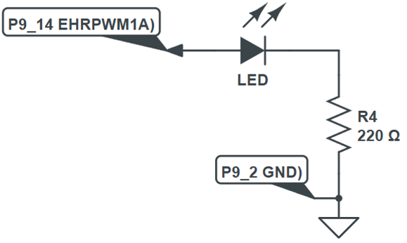
Run the code file to see if RGB Led changes colour, remember to wire up:
-
If all is well, and you have connected up your circuity correctly, the LED should show 100% then 50% then 10% and off, also this terminal output