Cat RJ45 Cables
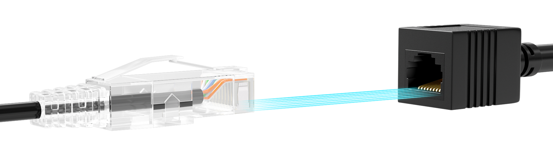
An RJ45 (Registered Jack 45) connector is a standardised interface commonly used for ethernet cable connections in wired networks. It has eight pins designed to accommodate the eight individual wires inside a standard ethernet cable.
They connectors are extensively used to connect network devices such as;
- computers,
- routers,
- switches,
- and keystone jacks.
The RJ45 connectors come in two primary types:
-
Shielded RJ45 connectors help minimize electromagnetic interference (EMI), which is useful in environments with high levels of interference.
-
Unshielded connectors are typically used in standard home networks and small office setups
An RJ45 connector uses eight pins to hold twisted pair cables, ensuring proper connection securely. Correct wiring and pinouts are critical for successful ethernet connections.
[!WARNING] Improper wiring can cause connectivity issues, slow network speeds, and data loss.
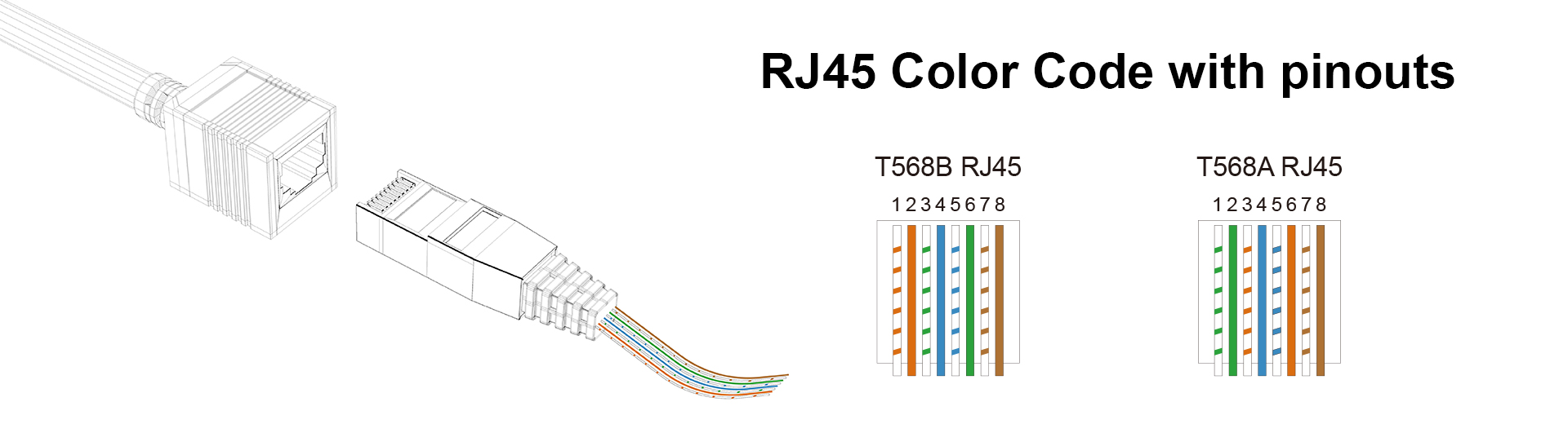
1. Standards of RJ45 Connector Color Code: T568A and T568B
There are two widely recognized color code standards for RJ45 cable wiring: T568A and T568B, both used to arrange the color-coded pairs in Ethernet cables like Cat6. Each color in these standards represents specific functions within the cable, determining data transmission paths. The striped ones are always odd-numbered pins and solid-colored ones are even-numbered pins.
In both T568A and T568B, the White/Blue (Pin 4), Blue (Pin 5), White/Brown (Pin 7), and Brown (Pin 8) wires serve a similar role. These pairs are typically unused for data transmission in standard Ethernet cables but play an important role in Power over Ethernet (PoE) setups, providing power to devices such as security cameras and VoIP phones. If PoE is not being used, these pairs may remain idle but provide critical support in commercial applications.**
The primary difference between T568A and T568B lies in the swapping of the green and orange wire pairs. In T568A, the green pair is responsible for transmitting data, while the orange pair handles receiving. In T568B, this is reversed, with the orange pair transmitting and the green pair receiving. These standards are important for ensuring consistent wiring in Ethernet networks and avoiding miscommunication between devices, especially when using different standards on opposite ends of a cable.
T568A Color Code Table
| Pin Number | Color Code | Signal | Description |
|---|---|---|---|
| 1 | White/Green | Transmit + (Tx +) | Transmits data |
| 2 | Green | Transmit - (Tx -) | Transmits data |
| 3 | White/Orange | Receive + (Rx +) | Receives data |
| 4 | Blue | Unused/PoE | Used for Power over Ethernet (PoE) |
| 5 | White/Blue | Unused/PoE | Used for Power over Ethernet (PoE) |
| 6 | Orange | Receive - (Rx -) | Receives data |
| 7 | White/Brown | Unused/PoE | Used for Power over Ethernet (PoE) |
| 8 | Brown | Unused/PoE | Used for Power over Ethernet (PoE) |
T568B Color Code Table
| Pin Number | Color Code | Signal | Description |
|---|---|---|---|
| 1 | White/Orange | Transmit + (Tx +) | Transmits data |
| 2 | Orange | Transmit - (Tx -) | Transmits data |
| 3 | White/Green | Receive + (Rx +) | Receives data |
| 4 | Blue | Unused/PoE | Used for Power over Ethernet (PoE) |
| 5 | White/Blue | Unused/PoE | Used for Power over Ethernet (PoE) |
| 6 | Green | Receive - (Rx -) | Receives data |
| 7 | White/Brown | Unused/PoE | Used for Power over Ethernet (PoE) |
| 8 | Brown | Unused/PoE | Used for Power over Ethernet (PoE) |
2. For Straight Through
This configuration is used to connect different types of devices, such as a computer to a router or switch. In a straight-through cable, both ends are wired using the same color code standard, either T568A or T568B. This means the pin assignments are identical at both ends, allowing for direct communication between devices with different roles in the network (e.g., sending and receiving data).
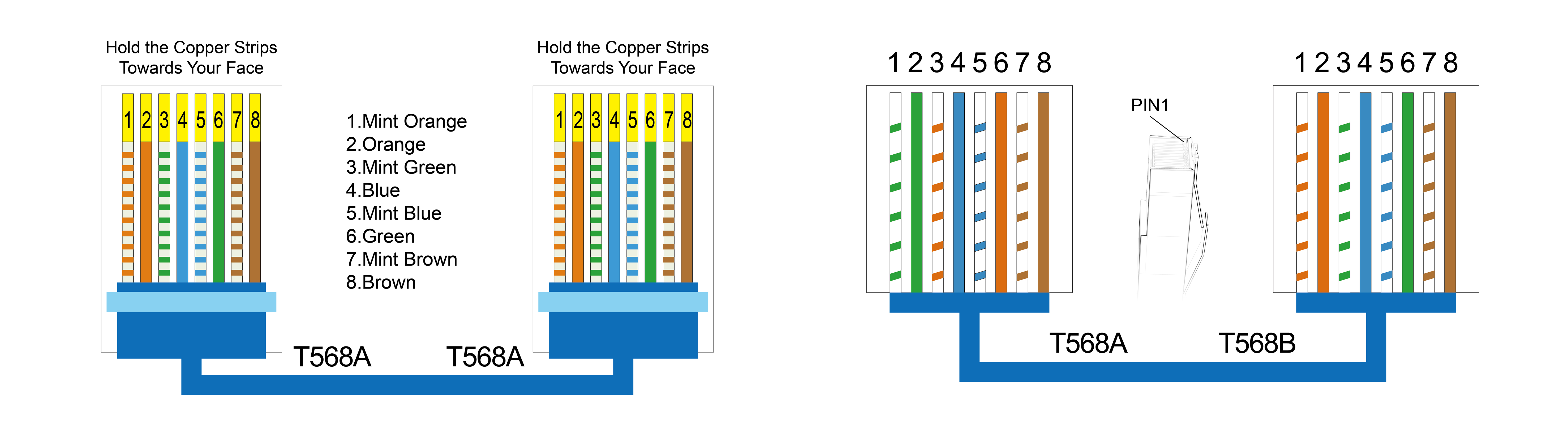
3. For Crossover Pinout
This configuration is used for connecting similar devices, such as two computers or two switches, directly without an intermediary device (like a router). In a crossover cable, one end is wired using the T568A standard, and the other end uses the T568B standard. This arrangement ensures that the transmit and receive wires are "crossed" so that the transmitting pins on one end connect to the receiving pins on the other, facilitating communication between the two devices.
4. Should You Use T568A or T568B?
When deciding between RJ45 Color Code A or B, the choice largely depends on compatibility with existing infrastructure and regional preferences. T568A is often used in environments that require backward compatibility with older systems, such as legacy telephone networks or government installations, commonly seen in Europe and the Pacific region. It is the preferred choice when projects involve older systems or require federal compliance due to its backward compatibility with older telecom systems.
On the other hand, T568B is more widely adopted in modern commercial and residential networks, aligning better with contemporary equipment and making it the default standard in most telecom installations, particularly in the United States.
For most setups, consistency is crucial. If you're expanding an existing network, it's best to stick with the current wiring standard. However, for new installations, T568B is often recommended due to its widespread use and better alignment with modern systems. Lastly, keep in mind that for straight-through cables, use the same standard at both ends, while for crossover cables, mix T568A and T568B to ensure proper data transmission.
5.Steps of Crimping RJ45 Cat5e Cable
-
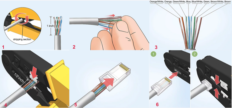
Strip the cable back 1 inch (25 mm) from the end. Insert the cable into the stripper section of the tool and squeeze it tight. Then, rotate the crimping tool around the cable in a smooth and even motion to create a clean cut. Keep the tool clamped and pull away towards the end of the wire to remove the sheathing.
-
The stripping section is a round hole near the handle of the tool.
-
The sheathing should come off cleanly, leaving the wires exposed.
-
-
Untwist and straighten the wires inside of the cable. Inside of the cable you’ll see a bunch of smaller wires twisted together. Separate the twisted wires and straighten them out so they’re easier to sort into the right order.
-
Cut off the small plastic wire separator or core so it’s out of the way.
-
Don’t cut off or remove any of the wires or you won’t be able to crimp them into the connector.
-
-
Arrange the wires into the right order. Use your fingers to put the wires in the correct order so they can be properly crimped. The proper sequence is as follows from left to right: Orange/White, Orange, Green/White, Blue, Blue/White, Green, Brown/White, Brown.
-
There are 8 wires in total that need to be arranged in the right sequence.
-
Note that the wires labeled Orange/White or Brown/White indicate the small wires that have 2 colors.
-
-
Cut the wires into an even line 1⁄2 inch (13 mm) from sheathing. Hold the wires with your thumb and index finger to keep them in order. Then, use the cutting section of the crimping tool to cut them into an even line.
-
The cutting section of the tool will resemble wire cutters.
-
The wires must be in an even line to be crimped into the RJ-45 connector properly. If you cut them in an uneven line, move further down the wires and cut them again.
-
[!TIP] Tip: If your tool doesn’t have a cutting section, use a pair of wire cutters or scissors to cut the small wires.
-
Insert the wires into the RJ-45 connector. Hold the RJ-45 connector so the clip is on the underside and the small metal pins are facing up. Insert the cable into the connector so that each of the small wires fits into the small grooves in the connector.
-
The sheathing of the cable should fit just inside of the connector so it’s past the base.
-
If any of the small wires bend or don’t fit into a groove correctly, take the cable out and straighten the wires with your fingers before trying again.
-
The wires must be inserted in the correct order and each wire must fit into a groove before you crimp the connector.
-
-
Stick the connector into the crimping part of the tool and squeeze twice. Insert the connector in the crimping section of the tool until it can’t fit any further. Squeeze the handles to crimp the connector and secure the wires. Release the handles, then squeeze the tool again to make sure all of the pins are pushed down.
- The crimping tool pushes small pins in the grooves down onto the wires to hold and connect them to the RJ-45 connector.
-
Remove the cable from the tool and check that all of the pins are down. Take the connector out of the tool and look at the pins to see that they’re all pushed down in an even line. Lightly tug at the connector to make sure it’s attached to the cable.
- If any of the pins aren’t pushed down, put the wire back into the crimping tool and crimp it again.