Blink
- Remember to include in your
PATHavr-gcc,avrdudeandmake - Open
~/.bashrcand add the following lines, then save and run the commandsource ~/.bashrcto update the current session with the newPATH- Uni machines
# ~/.bashrc export PATH=$PATH:"/c/ProgramData/arduino-ide-v2/Local/Arduino15/packages/arduino/tools/avr-gcc/7.3.0-atmel3.6.1-arduino7/bin" export PATH=$PATH:"/c/ProgramData/arduino-ide-v2/Local/Arduino15/packages/arduino/tools/avr-dude/6.3.0-arduino17/bin" export PATH=$PATH:"/c/Program Files/W64DevKit-V2.4.0/w64devkit/bin" - Your personal windows machine
# ~/.bashrc export PATH=$PATH:"/c/Users/YOURUSERNAME/AppData/Local/Arduino15/packages/arduino/tools/avr-gcc/7.3.0-atmel3.6.1-arduino7/bin" export PATH=$PATH:"/c/Users/YOURUSERNAME/AppDataLocal/Arduino15/packages/arduino/tools/avr-dude/6.3.0-arduino17/bin" export PATH=$PATH:"/c/Program Files/w64devkit/bin" - You can install w64devkit from here:
- Uni machines
1. blink.ino
-
So you are no doubt familiar with the well known
blink.ino:// the setup function runs once when you press reset or power the board void setup() { // initialize digital pin LED_BUILTIN as an output. pinMode(LED_BUILTIN, OUTPUT); } // the loop function runs over and over again forever void loop() { digitalWrite(LED_BUILTIN, HIGH); // turn the LED on (HIGH is the voltage level) delay(1000); // wait for a second digitalWrite(LED_BUILTIN, LOW); // turn the LED off by making the voltage LOW delay(1000); // wait for a second }There is a lot of abstraction happening here, where are the ports/registers?
Let’s now turn this into an embedded program!
2. Create blink.c
-
Create a new directory called
embeddedCand a child directoryblink -
Create a new file inside the the
blinkdirectory calledblink.c -
Now it’s time start wrighting out the program:
#include <avr/io.h> // provides macros and definitions for accessing registers and hardware-specific functions of AVR microcontrollers #define F_CPU 16000000UL #include <util/delay.h> // provides delay functions, including _delay_ms() for millisecond delays #define BLINK_DELAY_MS 2000 int main (void) { // Arduino digital pin 13 (pin 5 of PORTB) for output DDRB |= 0b00100000; // PORTB5 while(1) { // turn LED on PORTB |= 0b00100000; // PORTB5 _delay_ms(BLINK_DELAY_MS); // turn LED off PORTB &= ~ 0b00100000; // PORTB5 _delay_ms(BLINK_DELAY_MS); } }|=operator is used to set (turn on) specific bits without changing others. It performs a bitwise OR operation with the current value of a register, setting only the bits t correspond to 1 in the mask.-
// Initial value: all bits are 0
uint8_t register_value = 0b00000000;
    // Set bit 2
register_value |= (1 << 2); // 0b00000100
    // Result: register_value = 0b00000100 (Bit 2 is now set)
&= ~to clear (turn off) a specific bit, we use the &= operator combined with the bitwise NOT~. This combination creates a mask where only the desired bit is set to 0, le all other bits are 1. The&=operation then turns off the targeted bit without affecting others
-
// Initial value: all bits are 0
uint8_t register_value = 0b00000000;
    // Set bit 2
register_value &= ~(1 << 2); // 0b11111011
    // Result: register_value = 0b00000000 (Bit 2 is now set)
-
3. Compiling: Object file
-
We need to compile the code so that it can be uploaded to the atmega328p chip:
- we are going to be using the
avr-gcccompiler to first create the object file:
-
-Os-
-mmcu=atmega328pconfigures the compilation process to generate code compatible with the ATmega328P’s specific architecture, instruction set, and memory layout -
-DF_CPU=16000000ULthe-Doption defines a macro (F_CPU) that will be used in the code, similar to adding#define F_CPU 16000000UL(16MHz) at the top of `blink. -
-cflag tells avr-gcc to compile the source file into an object file (.o) rather than a full executable -
-ospecifies the output file for the compilation.-oallows you to name the output file, which in this case isblink.o
-
- we are going to be using the
-
Exploring the object file, run the following the command
avr-objdump -d -S blink.o:output
blink.o: file format elf32-avr Disassembly of section .text.startup: 00000000 <main>: 0: 25 9a sbi 0x04, 5 ; 4 2: 2d 9a sbi 0x05, 5 ; 5 4: 2f ef ldi r18, 0xFF ; 255 6: 87 ea ldi r24, 0xA7 ; 167 8: 91 e6 ldi r25, 0x61 ; 97 a: 21 50 subi r18, 0x01 ; 1 c: 80 40 sbci r24, 0x00 ; 0 e: 90 40 sbci r25, 0x00 ; 0 10: 01 f4 brne .+0 ; 0x12 <main+0x12> 12: 00 c0 rjmp .+0 ; 0x14 <main+0x14> 14: 00 00 nop 16: 2d 98 cbi 0x05, 5 ; 5 18: 2f ef ldi r18, 0xFF ; 255 1a: 87 ea ldi r24, 0xA7 ; 167 1c: 91 e6 ldi r25, 0x61 ; 97 1e: 21 50 subi r18, 0x01 ; 1 20: 80 40 sbci r24, 0x00 ; 0 22: 90 40 sbci r25, 0x00 ; 0 24: 01 f4 brne .+0 ; 0x26 <main+0x26> 26: 00 c0 rjmp .+0 ; 0x28 <main+0x28> 28: 00 00 nop 2a: 00 c0 rjmp .+0 ; 0x2c <__zero_reg__+0x2b>-
line 6
sbi 0x04, 5: Set bit5in the I/O register at address 0x04, typically used to configure a pin as an output. Thesbiinstruction sets a specific bit in an I/O register. -
line 8
ldi r18, 0xFF: Load the constant0xFF(255 in decimal) into registerr18. This sets up a value, often for delays or looping. -
line 11
subi r18, 0x01: Subtracts 1 from r18. This, along with thesbciinstructions, forms a delay loop by decrementing registersr18,r24, andr25until they reach zero. -
line 14
brne .+0: Branch if not equal (loop back if r18, r24, or r25 is non-zero). The program will keep looping here to create a delay. -
line 15
rjmp .+0: Relative jump (infinite loop). This is often used to create a long delay or an idle state. The program will stall here until an external reset or interrupt occurs. -
line 17
cbi 0x05, 5: Clear bit 5 in I/O register0x05, likely to turn off the LED. -
ldi,subi,sbci, andbrneform delay loops by decrementing registers until they reach zero. -
rjmpandnopprovide additional delays or idle periods
All information can be found here for ISA AVR Instruction Set
-
4. Compiling: .elf (Executable and Linkable Format) file
-
Now we can make the
.elf(Executable and Linkable Format) file, run the following code: -
Exploring the object file, run the following the command:
blink.elf:     file format elf32-avr

Sections:
Idx Name          Size      VMA       LMA       File off  Algn
0 .data         00000000  00800100  000000B0  00000124  2**0
                CONTENTS, ALLOC, LOAD, DATA
1 .text         000000B0  00000000  00000000  00000074  2**1
                CONTENTS, ALLOC, LOAD, READONLY, CODE
2 .comment      00000011  00000000  00000000  00000124  2**0
                CONTENTS, READONLY
3 .note.gnu.avr.deviceinfo 00000040  00000000  00000000  00000138  2**2
                CONTENTS, READONLY
4 .debug_aranges 00000020  00000000  00000000  00000178  2**3
                CONTENTS, READONLY, DEBUGGING
5 .debug_info   000006af  00000000  00000000  00000198  2**0
                CONTENTS, READONLY, DEBUGGING
6 .debug_abbrev 000005b6  00000000  00000000  00000847  2**0
                CONTENTS, READONLY, DEBUGGING
7 .debug_line   0000007c  00000000  00000000  00000dfd  2**0
                CONTENTS, READONLY, DEBUGGING
8 .debug_str    00000208  00000000  00000000  00000e79  2**0
                CONTENTS, READONLY, DEBUGGING
Contents of section .text:
0000 0c943400 0c943e00 0c943e00 0c943e00  ..4...>...>...>.
...
Contents of section .comment:
...
Contents of section .note.gnu.avr.deviceinfo:
...
Contents of section .debug_aranges:
...
Contents of section .debug_info:
...
Contents of section .debug_abbrev:
...
Contents of section .debug_line:
...
Contents of section .debug_str:
...
5. Compiling: hex file
-
Now we need to create the
.hexfile to be burned to the atmega328p:avr-objcopyis a tool that copies and converts object files. In AVR development, it’s commonly used to convert compiled.elffiles into formats suitable for uploading to microcontrollers, such as Intel HEX-O ihexoption specifies the output format.-Ostands for “output format,” andihexrefers to Intel HEX format.
-
Now you can look inside the hex code:
blink.hex: file format ihex Sections: Idx Name Size VMA LMA File off Algn 0 .sec1 000000B0 00000000 00000000 00000000 2**0 CONTENTS, ALLOC, LOAD Contents of section .sec1: 0000 0c943400 0c943e00 0c943e00 0c943e00 ..4...>...>...>. 0010 0c943e00 0c943e00 0c943e00 0c943e00 ..>...>...>...>. 0020 0c943e00 0c943e00 0c943e00 0c943e00 ..>...>...>...>. 0030 0c943e00 0c943e00 0c943e00 0c943e00 ..>...>...>...>. 0040 0c943e00 0c943e00 0c943e00 0c943e00 ..>...>...>...>. 0050 0c943e00 0c943e00 0c943e00 0c943e00 ..>...>...>...>. 0060 0c943e00 0c943e00 11241fbe cfefd8e0 ..>...>..$...... 0070 debfcdbf 0e944000 0c945600 0c940000 ......@...V..... 0080 259a2d9a 2fef87ea 91e62150 80409040 %.-./.....!P.@.@ 0090 e1f700c0 00002d98 2fef87ea 91e62150 ......-./.....!P 00a0 80409040 e1f700c0 0000ebcf f894ffcf .@.@............-
Sections
- Idx: Index of the section, here it’s 0 because there’s only one section.
- Name (.sec1): The name of this section, which is likely used for the program code.
- Size (000000B0): The size of this section in hexadecimal (0xB0, or 176 bytes).
- VMA (Virtual Memory Address): The address in memory where this section will be loaded, here it starts at 0x00000000.
- LMA (Load Memory Address): Where the section is loaded in flash memory, matching the VMA.
- File Offset (00000000): The offset in the file where this section’s data starts.
- Alignment (2**0): Specifies that there’s no special alignment needed.
-
sec1
0000 0c943400 0c943e00 0c943e00 0c943e00 ..4...>...>...>.- Address (
0000): This is the address in memory where the data on this line starts. - (
0c943400 0c943e00 0c943e00 0c943e00): These are the machine code instructions. Each group of 8 hex characters (4 bytes) represents an instruction0c9434000c94: This is aJMPorRJMP(Relative Jump) instruction.3400: The address to jump to
0c943e00- Each
0c94prefix also represents anRJMPor similar instruction. 3e00is the destination address of the jump.
- Each
- (
..4...>...>...>.): This shows an ASCII interpretation of the hex bytes, useful in some cases for debugging, though often unreadable
- Address (
-
6. Uploading Blink
-
Now its time to upload the code:
-
Uni machine:
-
Your personal machine:
$ avrdude -C "C:\Users\YOURUSERNAME\AppData\Local\Arduino15\packages\arduino\tools\avrdude\6.3.0-arduino17\etc\avrdude.conf" -c arduino -p atmega328p -P COM6 -b 115200 -U flash:w:blink.hex-Cis the path to the configuration file-cspecifies the programmer-pspecifies the part no, ie the chipset-Pis the port, COM# (Windows) or /dev/ttyACM# (Linux)- Windows getting the correct port run:
$ wmic path Win32_SerialPort get caption, name, deviceID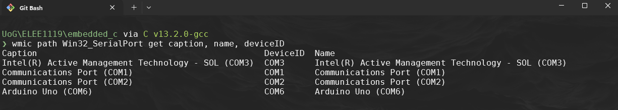
- Linux use
dmesgorlsusb
- Windows getting the correct port run:
-bspecifies the baudrate, overrides default RS-232-Umemory operation, ie,flashis the memtype in which mode,r,w,vand then the file
-
-
You should now see the BUILT-IN LED flashing on the board every 2 seconds.
-
To make life easier going forward we should use a Makefile:
MCU = atmega328p F_CPU = 16000000UL CC = avr-gcc CFLAGS = -Os -mmcu=$(MCU) -DF_CPU=$(F_CPU) OBJCOPY = avr-objcopy AVRDUDE = avrdude AVRDUDECONFIG = "C:\ProgramData\arduino-ide-v2\Local\Arduino15\packages\arduino\tools\avrdude\6.3.0-arduino17\etc\avrdude.conf" PORT = COM6 BAUD = 115200 PROGRAMMER = -c arduino -p $(MCU) -P $(PORT) -b $(BAUD) all: blink.hex blink.hex: blink.elf $(OBJCOPY) -O ihex -R .eeprom $< $@ blink.elf: blink.o $(CC) $(CFLAGS) -o $@ $< blink.o: blink.c $(CC) $(CFLAGS) -c -o $@ $< upload: blink.hex $(AVRDUDE) -C $(AVRDUDECONFIG) $(PROGRAMMER) -U flash:w:blink.hex clean: rm -f blink.o blink.elf blink.hex -
Now every time we modify
blink.cyou can use theMakefilemake cleanmakemake upload